Fresnel Zones
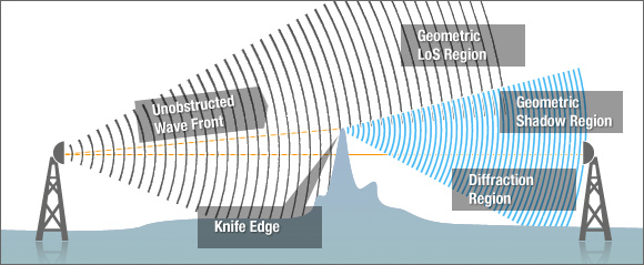
Fresnel Zone discussion is quite complicated and complex but the concepts should be quite easy to understand. There are a few phenomena that you must understand, the first is Huygens wave principles which states that waves will start to form new circular waves at each point of a wave front. Simply put, if the wave hits an object point in space, circular waves would be diffracted outwards and forwards in a semi-circular fashion as shown by the diagram below:
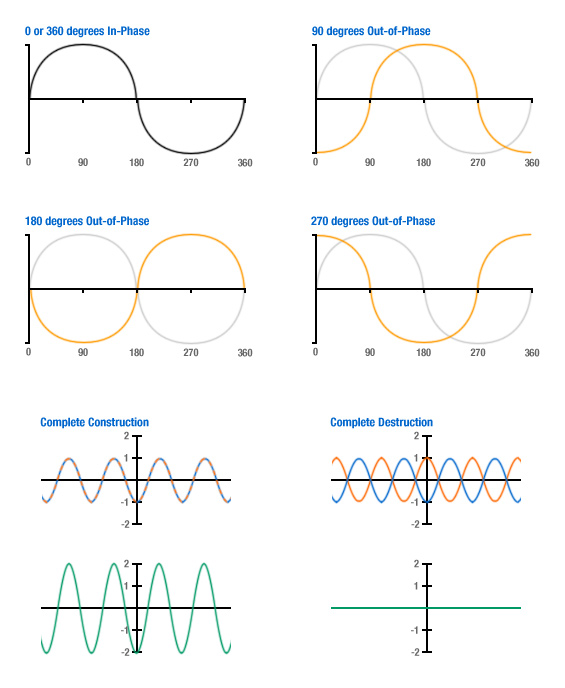
Secondly, all RF signal beams widen as they propagate through the air; the angle at which they widen can be limited by directional antennas. Lastly, signals can interfere with each other, especially at similar frequencies, due to waves being out of phase with each other. This phase shift is calculated between 0 and 360 degrees with complete in-phase occurring at 0 and 360 degrees and complete out-of-phase at 180 degrees. Waves superimpose themselves upon each other and those that are in-phase undergo constructive interference with their signal's amplitude adding together to create a stronger signal but the out-of-phase signals experience destructive interference reducing the signal's amplification up to the point of complete annihilation, if identical but 180 degrees out of phase. This can be easier to understand visually as shown by the diagrams below:
The theory of Fresnel Zones takes a direct line between the two operating Wireless Networking devices with Points A and B at each end and also the three dimensional space around the line that affects the signal contributing to the receiving end. Some of the signal travels directly along the path from A to B whilst other waves travel off of this straight line on paths off axis which results in their transmission paths to be of a longer distance causing phase shift between these different beams. By introducing the concepts explained above and applying some calculations it is found that there are ellipsoidal ring zones found to be located around the direct AB path which have an effect on the signal strength experienced by the receiver.
There are an infinite number of calculable Fresnel Zones but the Fresnel Zone that has most effect on the performance of the Wireless Network is the 1st Fresnel Zone. If there are any obstructions, such as buildings, trees or hills, located in this 1st Fresnel Zone, the signal will be affected by these and would therefore be weakened at the receiver. As a rule of thumb, when planning wireless links, the 1st Fresnel Zone should always be clear of obstruction but this can be impractical so it is said that no more than 40% should be obstructed i.e. 60% clear, but it is recommended for optimum performance it should be no more than 20% or less blocked. Note that obstacles in the 1st Fresnel Zone will create signals that will be 0 to 90 degrees out of phase, 90 to 270 degrees out of phase in the second zone, 270 to 450 degrees out of phase in third zone and so on.
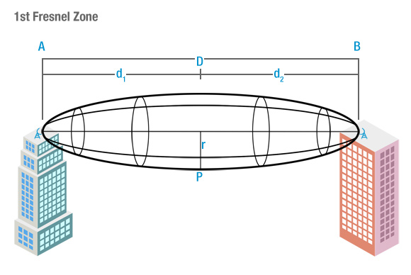
To calculate Fresnel Zones for your Wireless Network, first establish the RF LoS (Line of Sight) which is the direct, straight line between the transmitter and receiver (or transceivers) antennas. The general equation for calculating the Fresnel Zone radius at any point P in between the endpoints of the wireless link can be shown by the following equation:
Where,
 The nth Fresnel Zone radius (m)
 The distance of P from Point A (m)
 The distance of P from Point B (m)
 The wavelength of the signal (m)
The radius of the Fresnel Zone is at its highest value (greatest distance) directly at the centre of the RF LoS and for the practical application of planning Wireless Networks, it is useful to know the maximum radius of the 1st Fresnel Zone.
Therefore the distances between Point A and B to P will be identical and by converting the wavelength value to signal frequency we can say the following:
Where,
 Speed of light in a vacuum (3x10⁸ms-1)
 Total Distance (m)
 Signal frequency (Hz)
Therefore if the values for frequency and total distance are converted to GHz and km respectively, the equation for the maximum radius of the 1st Fresnel Zone can be derived in the following manner:

Example 1:
If calculating the maximum radius of the 1st Fresnel Zone of a 500m link operating at 5.5GHz (5GHz 802.11n Channel 100):

If the antennas for the two devices were located 10m above ground (assuming that both locations were the same height above sea level) the 1st Fresnel Zone would pass 7.39m above ground at its widest point.
To calculate the 60% clear Fresnel Zone radius the following equation must be used:
So for our example this would calculate to be:
By subtracting this figure from the antenna height, you can calculate the maximum height of any obstruction between the devices within the 60% clear Fresnel Zone.
Maximum Obstruction Height = 10 - 2.02 = 7.98m
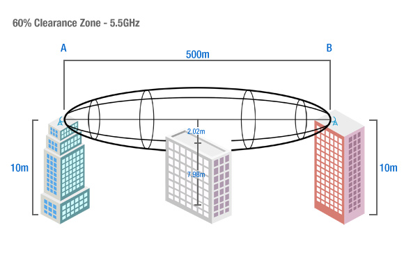
Therefore the maximum permissible height of any obstruction located within the RF LoS between the two devices, 500m apart, operating at 5.5GHz, at antenna heights of 10m with a minimum clearance Fresnel Zone of 60% is 7.98m.
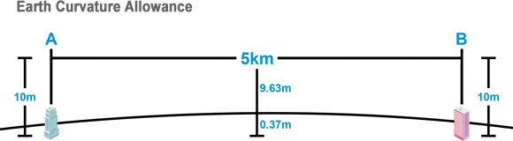
For links that are travelling over long distances (especially over 1km) the curvature of the Earth should be taken into account. As the Earth's surface curves, the bulge in between the two links (more technically the area in between the chord made between the two devices) becomes a Fresnel Zone obstacle within its own right and can impede upon the Fresnel Zones even if there are no other apparent obstacles.
The formula for calculating the effect of the Earth's radius is as follows:

Where,
 Height difference of Earth's Curvature at the mid-point between the two devices (m)
- Total Link Distance between the two devices (km)
 Effective Radius of Earth (km) Note: Usually taken as
  (1.333 rec.)actual radius to account for atmospheric refraction i.e. 8,504km
Example 2:
If calculating the maximum difference in height due to the curvature of the Earth between the two devices that 5km apart:
So you can see that at 5km apart, the Earth raises 0.37m at its maximum point due to its curvature and this can be factored in to your planning to ensure optimum performance. The easiest solution to counteract this issue is to raise the antennas of both devices to raise the Fresnel Zone.
Shown below, a small table is located showing the allowances that must be made due to the curvature of the Earth at various distances:
Link Distance (km) |
Curvature Allowance (m) |
| 1 |
Negligible |
| 2 |
Negligible |
| 3 |
0.2 |
| 5 |
0.4 |
| 10 |
1.5 |
| 15 |
4 |
| 20 |
6 |
| 25 |
10 |
| 30 |
13 |
| 35 |
18 |
| 40 |
24 |

 therefore